Garrattfan's Modelrailroading Pages

LTM 51 in HO
Drive unit: gearbox and motor
In the last week of my June holiday the gearboxes had arrived, and boy were they worth the wait! One minor thing though was the absence of any kind of manual. I reverted to the manual of another gearbox I had built for my NS 5000 and that just worked out fine. In the meantime I sent an e-mail to High Level Kits and within no time I got the manual in PDF form with an apology. Good service. |
|
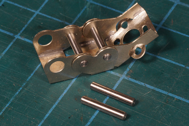 |
An hour after the arrival I had already advanced quite a bit, even without the manual. |
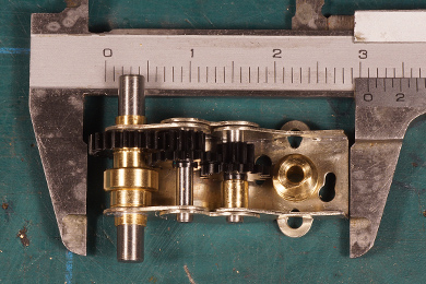 |
And in no time it looked like this. And running like a dream straight out of the box. |
Now came the moment of truth. Before ordering these gearboxes I had long been fiddling with drawings in 1:87, combining the general plan of LTM 51 with the profiles of the available High Level Kits gearboxes into the options listed below
|
|
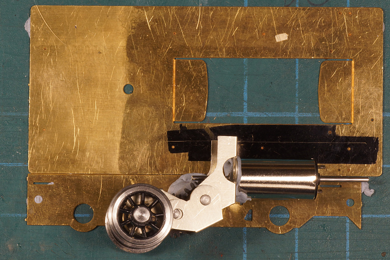
It fits! My dear friend BluTack helped matching it with the frame to assess the fit for final confirmation. The scribed line indicated the maximum available height in the engine room. |
|
 |
|
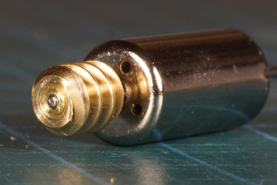 |
One issue to solve is that the motor has 1.0 mm spindle and the worm has a 2.0 mm bore.
So I turned a piece of 3.0 mm brass rod to a press fit in the worm, drilled it 0.9 mm and reamed the hole to fit snugly over the motor spindle. |
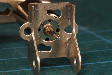 |
The second issue to address was that the spindle bearing / collar was 2.0 mm and the gearbox was designed for Mashima motors with a spindle bearing of 5.0 mm. Moreover I had nothing in the way of threaded holes to mount the motor. So I had make an adapter plate. |
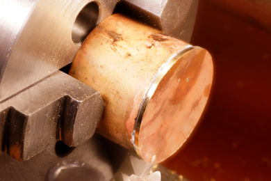 |
I retrieved a piece of scrap brass tube, remainder of my boiler making, faced both sides and soldered a 0.75 mm brass plate on it. |
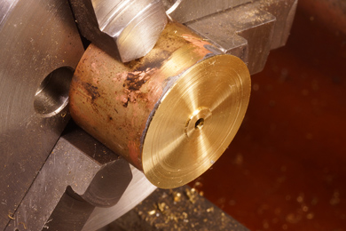 |
I turned it to about half the thickness leaving a 5 mm wide boss in the middle and I drilled a hole of 2.0 mm. |
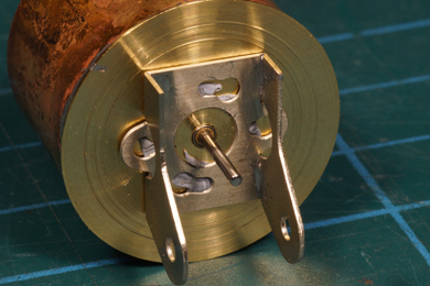 |
Well, that should nicely fit.
|
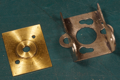 |
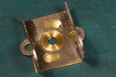 |
| I unsoldered the adapter plate and filed it to match the gearbox's motor mount. | |
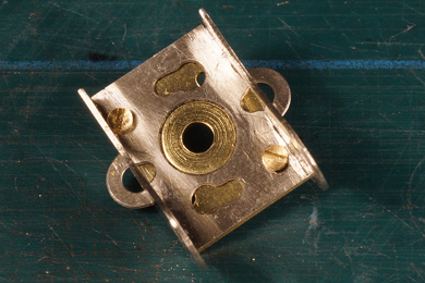 |
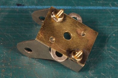 |
A hole adventure At first I drilled two holes to match the Mashima-holes. But then the bolts would not clear the motor. So I drilled two new holes in the adapter plate and two matching ones in the motor mount to clear the motor. I also soldered two nuts on the backside of the adapter plate, as the sheet metal alone was too thin for a thread M 1.0 |
|
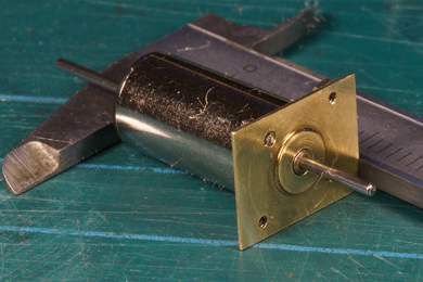 |
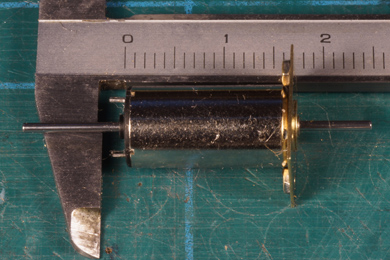 |
| Very thin (0.4 mm) but surprisingly strong. The motor was mounted on the adapter plate with a droplet of epoxy. | |
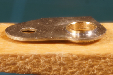 |
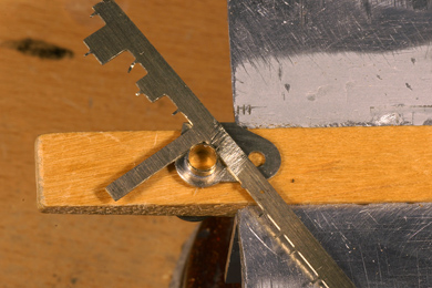 |
| On one half of a laundry peg, the bearing of the powered axle are filed down to approximately 0.5 mm. I use an angled scrap piece of brass or nickel silver for the height. | |
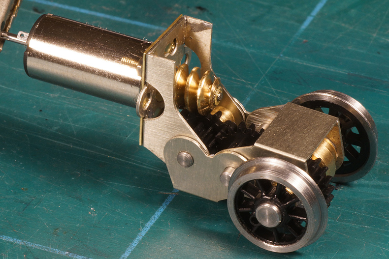
And there we are. Motor firmly mounted to the gearbox |
|

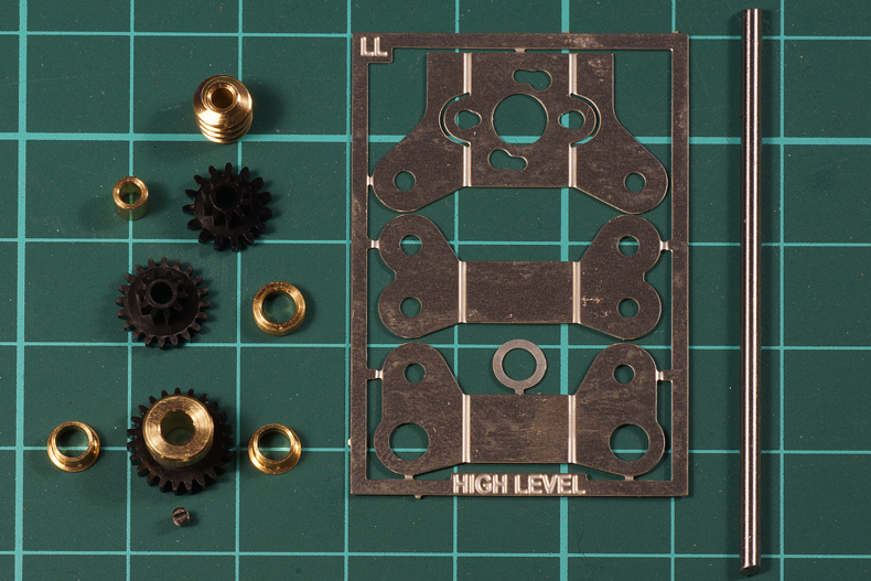

Sign my
GuestBook