Garrattfan's Modelrailroading Pages
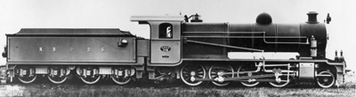
NBDS 118-119
Tender

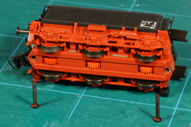
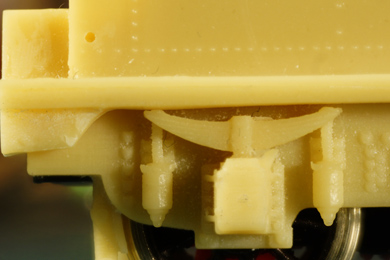
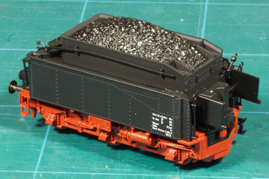
One last view of the complete tender as supplied by Roco. |
As already related before I bought two donor locomotives.
I used the frame of the first locomotive for the locomotive proper. Having arrived at this stage of the build I needed to rob the tender of the second locomotive from its gears. In fact the gears are the only parts I really needed from this model. |
As the second loco is a depiction of BR57 as it ran in the Netherlands in 1945-1947 I might just as well keep it for display purposes. Maybe one day I will order the gears as spares from Roco and restore the loco to running order. |
|
 |
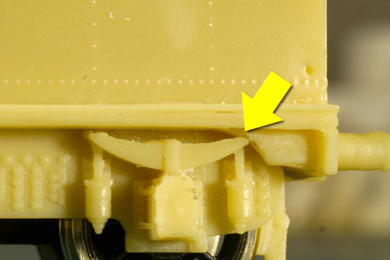
Contrary to most locomotives it is easy to spot how the tender can be disassembled. Just two bolts. |
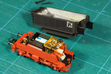 |
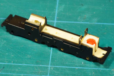
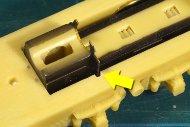
The superstructure is separated. |
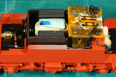 |
A view on the motor. The original Roco motor is big and clunky. It is possible to build the kit with this motor if you don't want to invest any further in this kit of if you shy away from or lack the experience replacing this motor. I ordered a Mashima 1630 from MK Modelbouwstudio. It has several advantages over the original Roco motor
|
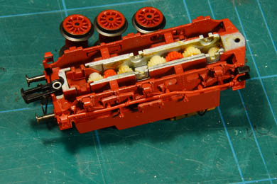 |
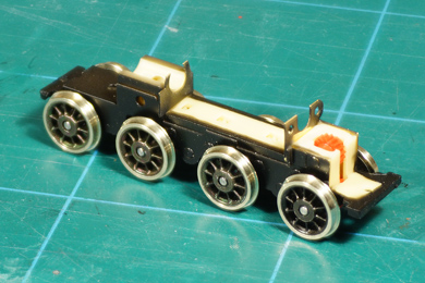
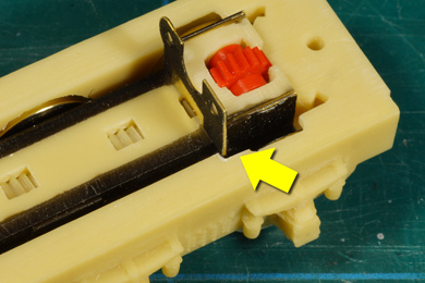
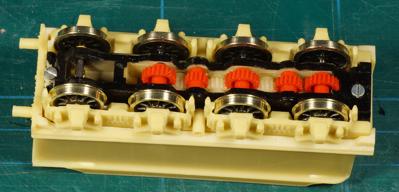
The gears are laid free. They are contained in a kind of separate gearbox ... |
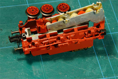 |
... which can be lifted ... |
 |
... out of the tender without further hassle. |
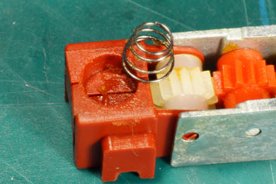 |
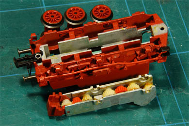
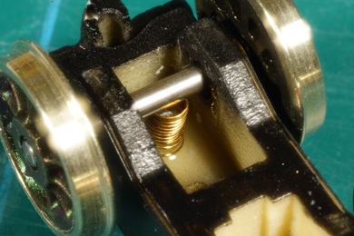
If you turn the gearbox over, that is "wheels down", you will find a spring that presses the third axle independently on the rails. Ingenious. Retrieve it before it wanders off into the world |
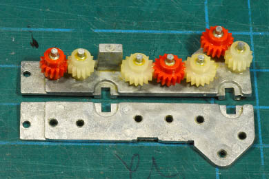 |
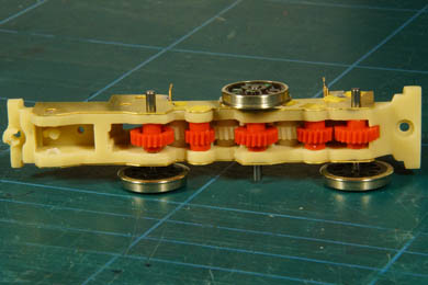
This is how the gears are laid out originally (just for the record, I want to remember it when I restore the original locomotive) |
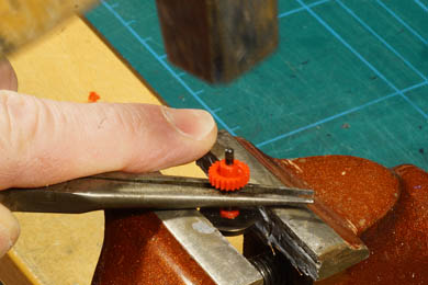 |
The axle gears need to be taken off. Although they not very firmly stuck, yet you need to persuade them into moving. The photo shows how I supported the gear with my longnose pliers on the vise. With a few gentle (really gentle!) taps with the hammer and the axle surrendered. |
 |
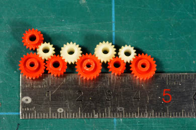 |
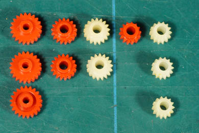
Inventory:
The right hand photo shows how they will go in the new tender. Close lookers will note that one small white gear is not there. Well, it s not needed and therefor stored in the reassembled original tender. |
|
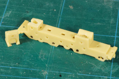 |
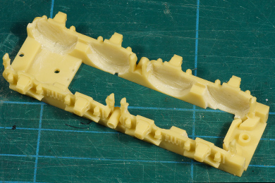
Now work on the tender frame starts. The tender is able to take two different types of motors: the older Roco two-wormed motor on the one hand. And either the new Roco single-wormed motor or a replacement on the other hand. As said I will install a Mashima so I will need only one worm "tower". The other one is sawn off. The manual advised that the whole gear tower can be removed in a single-worm situation but I will decide on that once I have the Mashima in the house. |
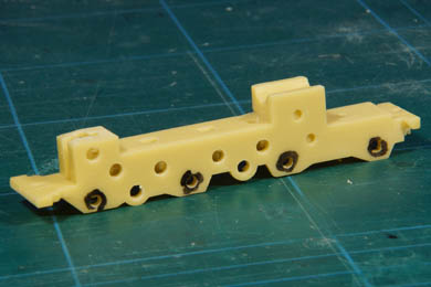 |
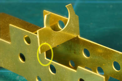
For clarity and to avoid confusion I marked the axle holes to distinguish them from the gear holes. They need to be drilled in a different diameter, axle holes 2.0 mm and the gear holes 2.5 mm. As the drilled holes are oversize anyway it actually is not very important. |
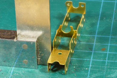 |
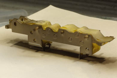
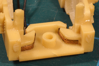
The brass overlay is folded and carefully squared before soldering. |
 |
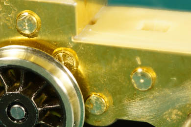
I always love the sight of fresh, clean brass. |
 |
Do not be confused if the motor attachment does not line up with the opposite side. It is not supposed to do so. |
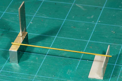
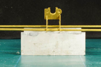
Check if the rod is straight |
The overlay needs a little twist (the left side is a bit closer) |
Because the brass overlay is the bearing part of the inner frame it is necessary to check if the overlay is straight and promises to put all wheels down on the rails. Two dead straight 2.0 mm rods are needed for this. To ascertain the rods are straight they are first laid on two metal bars and rolled (left). If the rod stops it sags showing it is bent and that the bend is on the DOWN side (gravity at work for you!). Correct and roll again until it rolls freely. Insert the rods through the axle holes of the first and the third axle (right). Look along the rods. If parallel everything is okay, otherwise twist the frame gently until satisfied. |
|
 |
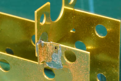 |
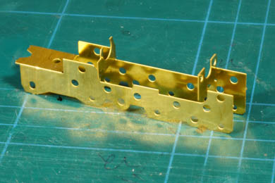
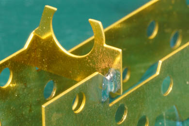
Then the etched folds and the two corners of the motor mounts are soldered. The rear motor mount needs a small 0.3 mm brass angle for strengthening. Yes, maybe I will remove this motor mount later, but for now I am taking no chances. Until the motor arrives and I can assess the impact of it I will act as if I will need this mount. The overlay and inner frame are now made to fit correctly. The overlay is fixed with a few strategic drops of epoxy. |
|
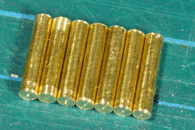 |
Seven gear axles cut and filed from the 2.5 mm brass rod provided with the kit.
Now ream all axle holes in the brass overlay.
WARNING: the etch work is only very slightly undersize. Actually only taking away the etch burs will in most cases suffice! It is delicate work, so time taken here is well spent. |
Assembling and testing |
One by one the gears are inserted and secured with a bit of masking tape in the inner frame (from now on including the overlay) Start testing immediately after inserting the first gear. It must run freely. Only then insert the second and test again and so forth. If a gear does not run freely remove it and find and eliminate the cause. When inserting the wheel axles through their axle gears I did not add the "other halve's" wheel to avoid wearing out the axle hole of the wheel face by repeated assembly and disassembly. |
 |
At this stage the inner frame should run without hesitation under the light push of your finger or under its own weight under a slanted cutting mat (on rails it is likely to derail) |
 |
Then the gears and wheel are removed and the intermediate gears are reinserted, adding a bit of epoxy glue on one side. Glueing one side only means the axle can still be disassembled if something happens to one of the gears. Although epoxy is a very powerful glue (with 200 kg/m2) it will softened with a 100C-150C soldering iron. You can push the axle out, of course in the direction of the glued side otherwise you will contaminate the gear.
Then the wheel axles are reinserted and the free running of the inner frame is tested for one last time. |
 |
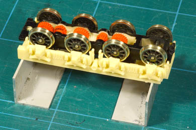
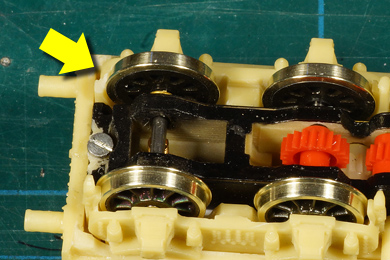
You may have noted that this tender has four axles where the BR57 tender had three. The NBDS tender has only three axles powered. The fourth is left free running and is sprung for better running. When checking for free running I found that this fourth axle touched on the body of the inner frame so some resin had to be removed. |
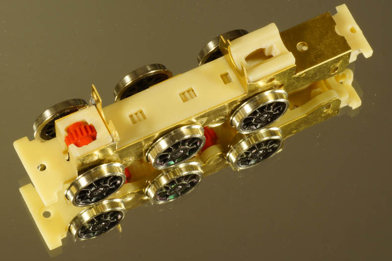
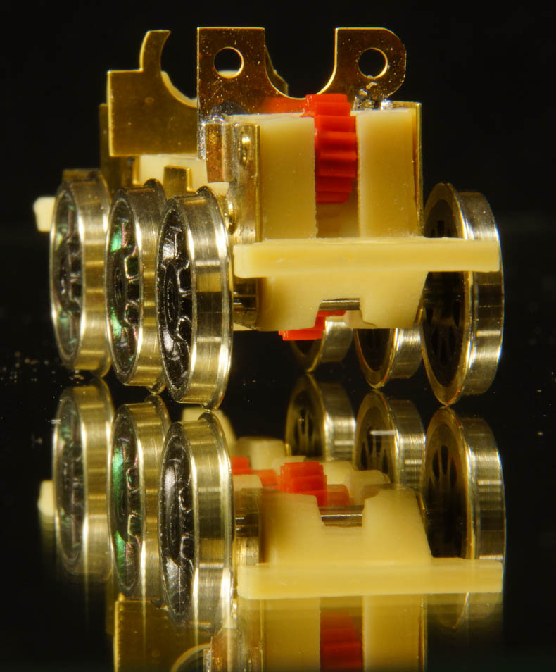
Once happy with all testing I assembled the three powered axles and put it on a mirror ... |
|
... to check if all six powered wheels touched on the glass. See for yourself. |
|
 |
 |
 |
Then the inner frame was sprayed black and varnished (Philotrain black and ditto semi-gloss varnish) and finally assembled. A small test revealed free running was not impeded. |
 |
The spring supporting the fourth axle by the way. |
| Now it is time to fit the outer frame on the inner frame. Before making it to do so it is better to first fit the styrene shims as noted in paragraph 8 of the manual, as demonstrated in the second photo below. I did not and I could have save me the double work of making is fit again after adding the shims. | |
 |
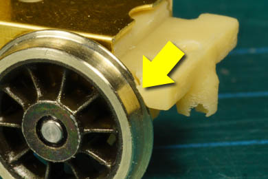
When fitting the outer frame I was in for a surprise. I did not expect the inner frame to fit in the outer frame immediately (this kit need a lot of attention as it comes to fitting). But I at least I expected that the axles would nicely fit between the outer frame's sides. In fact none of the axles did. |
 |
So I scraped away about a millimeter of the internal "splashers" to obtain sufficient clearance. I also needed to thin the brakeshoes. A lot of work and messy work for that but not difficult. Again taking time and working carefully is the magic recipe. |
 |
 |
 |
The manual says well after this stage to fit two shims to lift the outer frame one millimeter above the inner frame. Okay, but this could have better been done in advance, as noted above. |
 |
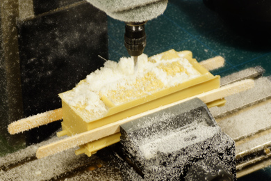 |
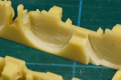
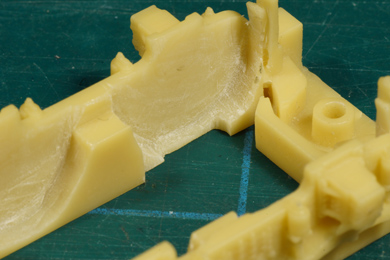
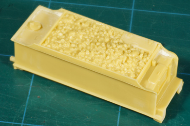
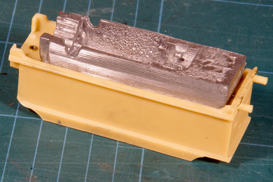
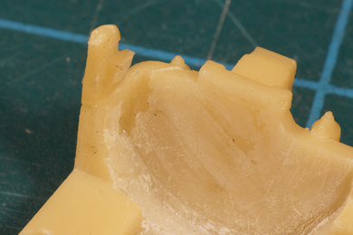
| The tender superstructure as supplied carried a full load of mock coal. I milled it away because I want to add real coal. Machine milling is messy business, wear a dust mask. Sawing with the piercing saw may be the better option. | |
 |
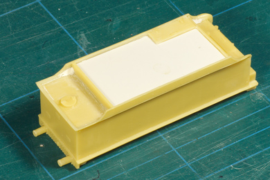 |
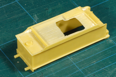
| I milled a tad too deep | So I was forced to provide a styrene insert |
| In hindsight I might better not have glued the insert in place. When the Mashima motor arrives I can evaluate the option of modelling a loco with part filled tender instead of fully topped up. We'll see what is possible. | |
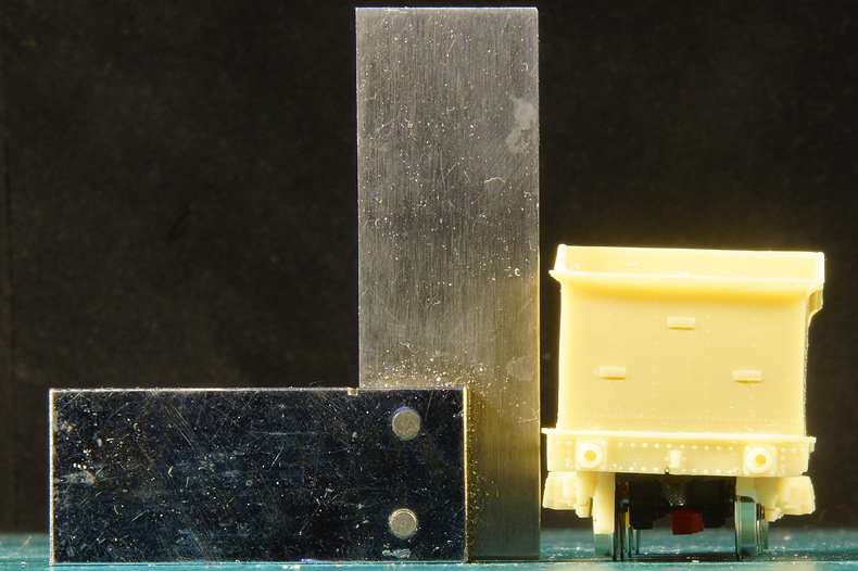
Checking the straight sitting of the superstructure. Always check if everything is square and fair if you add new parts to the main structure. And this saved the day when building the tender. After fitting the superstructure even with the naked eye I could spot "something" wrong and with the square next to it a substantial list was visible. In such cases remember these important lessons I learned (the hard way):
|
|
 |
 |
In my case the spring packet of the fourth axle "hung" on the valance of the superstructure. Removing a little material there diminished the list but did not (as I already forewarned in the text before these photos) relieve the problem entirely. So there should be a secondary cause!. |
|
 |
 |
| Then I found that the outer frame hung on the motor mounts. Making a slit now completely resolved the problem. It seems easy to tell, but for the record: it took me an hour to locate the three spots and to resolve the problem. | |
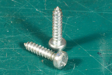 |
That resolved I turned my attention to the connection between superstructure and frame. The manual recommends to use two screws. I resented that for several reasons.
|
 |
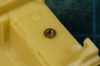 |
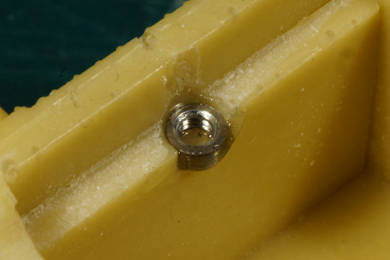
I decided to take another course and install a conventional bolt-nut connection. I took two M2 nuts and turned them round and down to 3.0 mm. I drilled two corresponding holes in the superstructure, carefully avoiding piercing through the outer surface and glued the rounded nuts with epoxy. |
|
Now the superstructure can repeatedly be mounted and removed without wear and without the risk of breakage. If I ever overtighten the bolt I will only pull out the nut. |
|
 |
 |
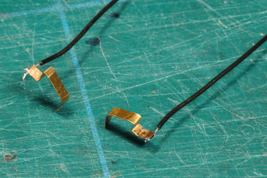
| The electrical wipers are made and glued into place. | |
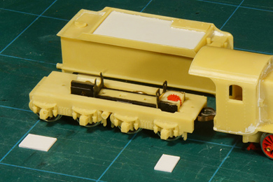
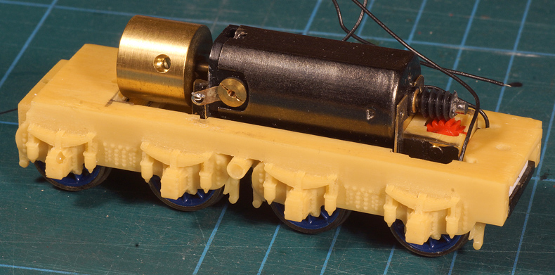
I ordered a replacement Mashima motor for better performance and added a Markits flywheel. Be careful that the motor leads do not touch the brass frame |
|
And so we have a good looking tender |
|
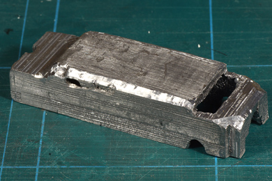
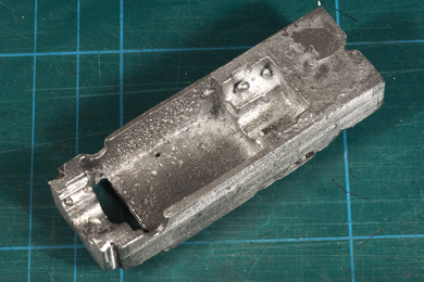
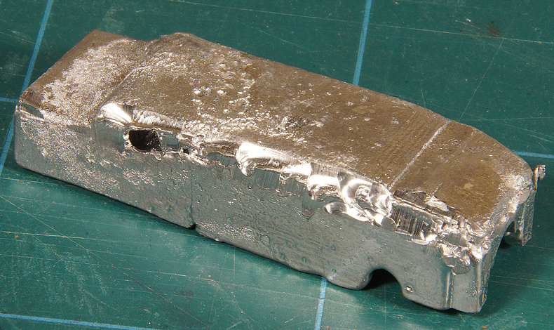
With the kit came a rather crude weight to load the tender. |
|
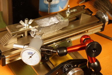 |
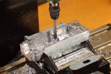
Nothing was true or square and the lump was clearly oversize. Initially it would not even fit in the body of the tender. After a bit of filing I decided that my mill would have to do the hard work.
A shot during milling the sides. Here the part is measured in to sit absolutely parallel on the cross table. |
 |
We have a fit! |
 |
The top and lower decks also needed some work. It took some fiddling and figuring where to take away material to let it settle all the way into the body. |
 |
 |
And the inside also needed a bit of attention to accommodate the motor and its flywheel. All in all I took off a liberal amount of material. |
|
 |
 |
| Now the end of the build neared I repaired an early stage breakage of one of the brake shoes. | |
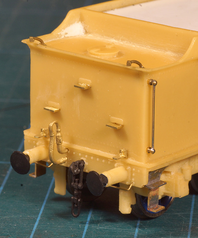 |
Detailing of the rear of the tender From top to bottom:
In total 23 parts! |
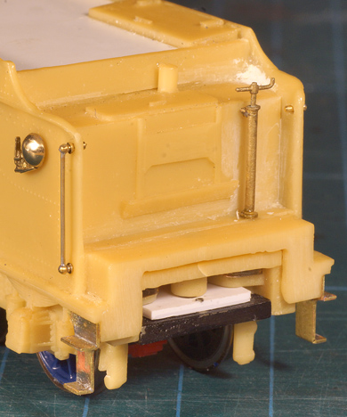 |
Detailing of the front of the tender
|


Sign my
GuestBook