Garrattfan's Modelrailroading Pages

SHM 26
Remotorising (2019)
The drive of the Philotrain SHM 26 kit was supplied in the form of a Tenshodo SPUD WB 26. As mentioned often during the build of this model the riding qualities of this thing were less than desirable, to say the least. After much tinkering and experimentation I was not able to make it run reliably, much to my frustration I must add. Finally I finished this model and put it in my display cabinet as a non-runner. It kept bugging me though and over time I kept searching for solutions mainly aimed towards building my own drive. I bought a Sagami drive with gearing in the hope I could somehow convert it to fit in the existing space. I couldn't. The main problem was the extremely restricted space. With only 26 mm between the axles and a fully closed footplate on top there was hardly any more space to fit anything else then another Tenshodo SPUD. Even other underfloor solutions were often just a tad bigger or higher.
After many thought on available solutions I decided to try and scratch build my own drive. I bought Alan Gibson wheels, sprung axle bearings, frame spacers, a motor from Tramfabriek and various belt drive parts from Nigel Lawton. I had a plan at last. I made my own frame plates from brass sheet. Then at some point I found I had made an recoverable error in drawing up the frameplates and progress stalled. My attention turned to other projects and the whole thing rested. |
|
Early attempts |
|
Top half: my scratch build attempt, with the smallest motor being from Tramfabriek. Bottom half,right: the Sagami drive which never took off |
|
The Universal Power Bogie kit |
|
| Then in January 2019, almost four years after the completion of the locomotive, while searching for something completely different, I stumbled over Mark Clark's Locosnstuff website which much too my amazement offered a kit as a SPUD replacement: the Universal Power Bogie. Some information required was quickly and kindly provided by Mark, the kit was duly ordered and a week later it landed on my doormat. | |
 |
|
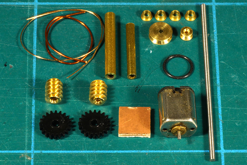
The contents of the package was simple enough. An etch with the frame plates, the spacers and an optional top plate and some washers. And a bag with drive components. The second (top) bag was added because I needed conversion bushes from the 2 mm axles to the 1/8" axle hole in the Alan Gibson wheels I already had. It also contained a longer layshaft as I wanted to add two tiny flywheels.
The included manual was simple enough, for anybody who ever built a loco almost everything is self-explanatory. Yet some fully adequate drawings clarify the few dark passages in the building process. Publication of the manual on this site was kindly granted by Mark Clark |
 |
The individual drive components |
|
Construction |
|
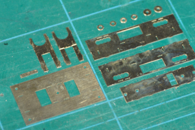 |
The parts are removed from the etch. Normally you keep parts on the etch as long as possible for easy identification but as there are so few in this kit it far easier to take it all apart as a first step. |
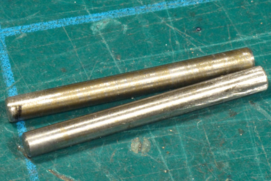 |
I sawed and filed two axles of 20.0 mm length from 2.0 mm steel rod. I chamfered the outer ends (break the edge, it is called in engineering terms). |
 |
A tad of cleaning up of the axle with fine steel wool was beneficial to the smoothness of the surface. |
The frame spacers were soldered into place. The frame plates offer multiple positions for the axle bearings to achieve the correct wheelbase. |
|
This is how the motor will fit into the frame. The ruler demonstrates how small the Universal Power Bogie is. I made this photo for demonstration purposes only. The manual clearly states to solder the second frame plate first and then slip the motor with a twist into place in the opening in the frame plates. I forgot an soldered the second frame with the motor still in place. A bit more fiddly, but then again it is a fiddly hobby. |
|
 |
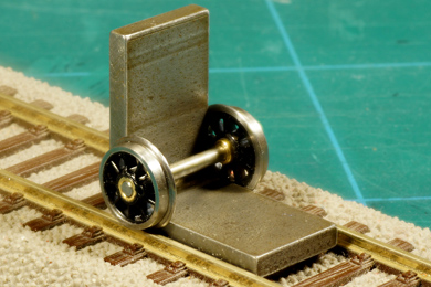 |
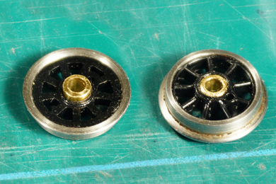
| The Alan Gibson wheels needed bushes to convert them from 1/8" (3.18 mm) to 2.0 mm. They are more or less press fit into the wheels with a slightest bit of epoxy glue to secure them. The wheels are not permanently fixed on the axles yet. The photo with the gauge is only for demonstration purposes. | |
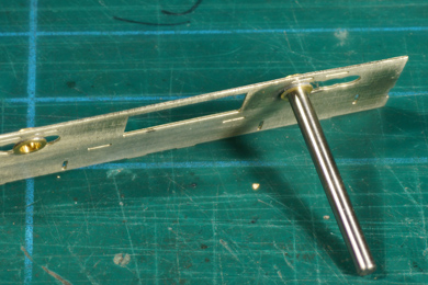 |
It is good engineering practise to make holes in bushes a bit undersize so do not be surprised if the axle does not fit into the bush instantly. |
 |
Ream the first bush turn by turn. Test fit the axle after every turn. It is the goal to ream a tiny amount past press fit so the axle turns freely. |
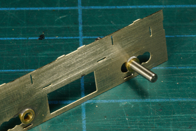 |
Once the axle fits in the first bush, mark the reamer with a water proof felt pen and the other bushes can quickly be reamed to the same size.
|
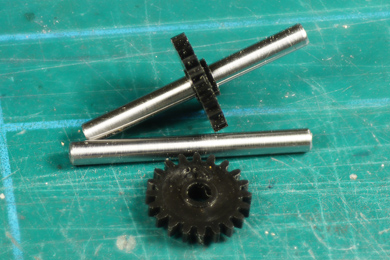 |
Same story for the delrin gears, now aiming for press fit. If that has been achieved, the gears are placed in the exact centre. A mark is made with a water proof felt pen. The gear is slid aside, a bit of epoxy glue is added and the gear is slid back into place working the epoxy under it.
|
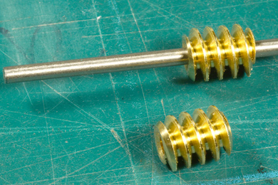 |
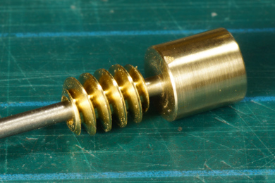
The holes in the brass worms are also a bit undersize. Although it would be technically desirable to aim for a press fit, it will in practice be difficult to press the worms on the layshaft when it is in the frame. So I opted to ream so they would just slide over the layshaft. They will be secured with epoxy later. As reamers are tapered, ream from both sides in equal measures so the narrowest point of the hole will be approximately halfway the worm. |
Now the motor is slipped into place and the second frame plate is soldered. Again: the manual clearly state FIRST solder the second frame plate in place and THEN slip the motor in with a twist. Typically a RTFM but I got away with it.Do not forget to insert the axles before soldering because you cannot get them in after soldering if you have already glued the delrin end gears in place. |
|
 |
 |
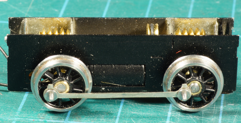
| Now is a good time to spray the power unit black. Once the wheels are in place this will become very difficult. | |
 |
I turned two 7 mm long 6 mm wide brass flywheels from brass rod, each weighing a diminutive 2 grams each! The centre hole is drilled undersize and reamed to fit the layshaft.
I could not make them any longer as they will then cover the screws that will hold the power unit to the superstructure. Neither could I make them any wider as they will become too high to fit under the superstructure. I hope four grams will make a visible difference. If it doesn't well, I tried :-) |
Again a photo for demonstration purposes (the belt drive isn't even there!), just to show where the flywheels will go. |
|
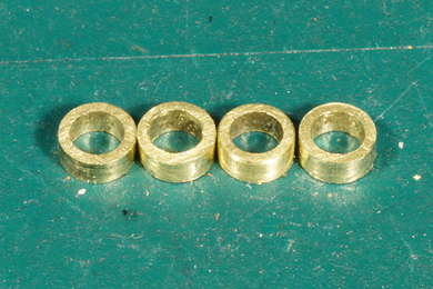 |
The frame is relatively narrow so pretty wide washers are made to fit between the wheels and the frame. I aimed to keep about 0.3 mm play |
 |
|
 |
The wheels are then prepared by adding the crankpins. |
 |
When glueing the wheels on one side you do not need to bother about quartering yet. |
 |
The third wheel is added and quartered approximately. You do not need to achieve an exact 90 degrees as long as the angles on both axles are the same. So 90 degrees by eye is good enough. For Dutch steam locomotives the rule of thumb is that the right hand leads, so the right wheel sits at three o'clock (pointing forward) when the left wheel is at twelve when looking at the face of the wheel.
I made two temporary coupling rods that exactly match the wheelbase of the loco. Once the glue of the third wheel had set completely I glued the fourth wheel, quartered it approximately and added the coupling rods. Then I gently pushed the loco over a piece of track. This movement forced the fourth wheel, with its glue still soft, to take the same position as the third wheel by the action of the coupling rods. Then I let the glue set. The fourth is now quartered in the very same position as the third wheel. |
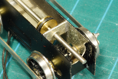 |
The layshaft is put into place at the same time adding the main pulley and the belt. Don't forget it, you won't be able to add it after this stage
First step in adding the worms is moving a washer over the layshaft. |
 |
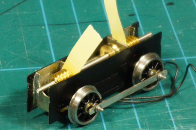
The trick here is glueing the worm and the worm alone. I use a greased paper shim for that. It serves two purposes:
The shim is pre-drilled with a hole of 1.3 mm, slightly less then the the shaft's diameter, so when moving it over the shaft the paper forms a tight, shallow collar. When placed the grease is added with a brush. |
 |
Then a bit of glue is put on the shaft. Although the paper shim should hold the glue in check there is no reason to be liberal with glue, we are talking droplets on pin points here! The worm is gently rocked back and forth over the shaft while moving forward.
|
 |
And so goes on the second worm, with one significant difference. You cannot rock the worms back and forth and move it forward, because the delrin gear is now blocked by the the other gear over the wheels and the coupling rods. And you need the keep the rods in place in order to keep the wheels synchronised. I you fail to do so you have the feedback over the coupling rods effecting both worms causing the unit to stall. So it is not only quartering that is utmost important but also synchronising. The trick to move the worm in place is turning clockwise, let the worm grab the delrin end gear and gently continue turning it until it reaches the paper shim. |
| After setting of the glue I removed the temporary coupling rods and added the original coupling rods from the kit. As these rods have liberal holes I did not expect any trouble with binding. I should have tested. I always say: always test. ALWAYS. I did not and was found to err. The unit stalled by binding. O dear, I wish I had taken the trouble to take sufficiently wide material for the temporary driving rods. I could have used them as a permanent solution. I decided to make a new pair. | |
 |
I measured out the same distance and drilled holes |
 |
The old coupling rod clearly shows the issue |
 |
Fully drawn |
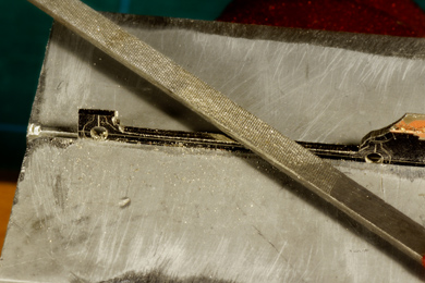 |
A bout of filing on two layers of nickel silver soldered together |
Done! Two new coupling rods |
|
Electric pickups |
|
 |
 |
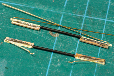 |
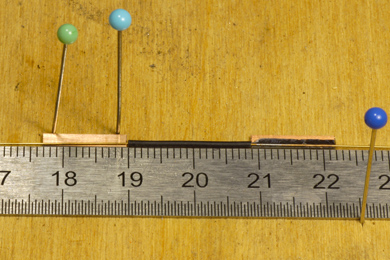
The electrical wipers were made of two 2.0 mm wide strips of copper clad circuit board which where soldered together with the base of the wiper. The piece of black insulation will keep the wiper off the motor and prevent a short. It also serves to space the two copper strips correctly during soldering.
|
 |
After soldering the wipers are bent up and over (left photo, top wire). They are cut to size and a head is bent into them so it neatly touches the inner rim of the wheels |
 |
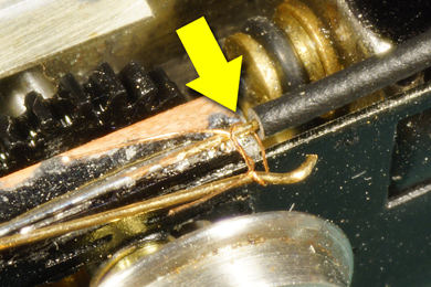 |
| I struggled to glue the wipers in place because the pressing action of the wiper would push the whole thing out of place. So I inhibited this action by tying each wiper up with a strand of copper wire that I previously pulled from the insulation. | |
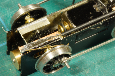 |
After the glue had set I removed the strand and wiper sprung into position. |
| After installing the wipers I could do some autonomous test runs and it ran well. | |
A home-made top plate |
|
 |
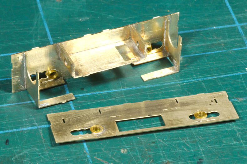
The supplied top plate (bottom) was too short for my appliction so I made a new top plate from 0.75 mm brass sheet. |
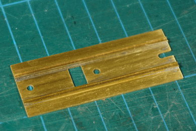 |
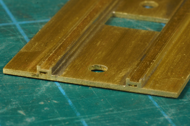 |
| After carefully measuring the width of the frame and lining it out on the brass I soldered two H-profiles on the bottom side of the top plate.. | |
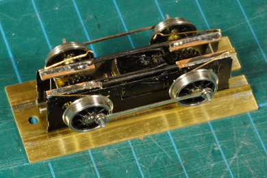 |
...between which the the frame is positioned and which will also provide the necessary grip for the epoxy glue |
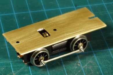 |
The square hole provides room for the main pulley which protrudes slightly above the frame |
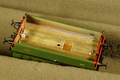 |
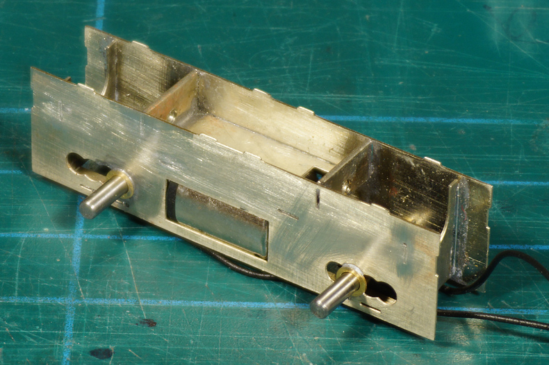
The top plate is placed in the superstructure, epoxy is applied and |
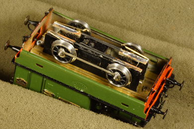 |
the Universal Power Bogie is placed and moved to the correct position. |
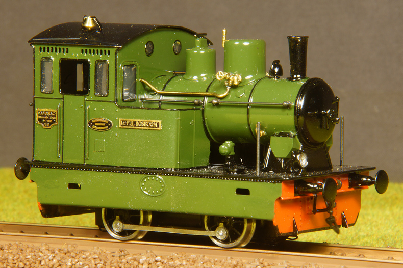
SHM 26 showing off its new hooves. She runs fine. |
|
The SHM 26 stabled along three other builds of mine. |
|






Sign my
GuestBook