Garrattfan's Modelrailroading Pages
Fairlie Merddin Emrys
7.6 Completion
My build of Merddin Emrys is drawing to a close. I have drawn up a list of chores that remain to be done to finish the actual construction before the painting process. A surprisingly short list I may say. This list was made by
As to the latter: I could account for most of the remaining parts as spares added in the frets or left overs from version choices. A few however were more mysterious and these were the subjects of a last bout of questions to EDM Models. None of these however proved to be a serious omission.
The paragraph headers on this page were on my remaining work list and the paragraphs were complemented as work progressed. |
|
Smokebox doors |
|
 |
 |
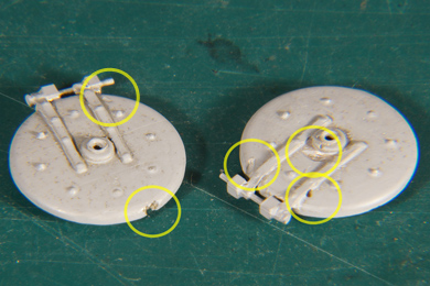
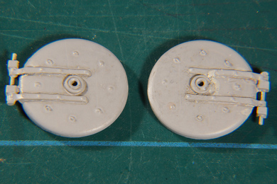
| Brass castings need close inspection for imperfections. An easy way to spot these imperfections is giving them a quick spray of grey primer, that highlights any dimples, creases or other misfit. And it worked. I expected to find two holes but I found three more. After inspection I cleaned the castings with cellulose thinner, dried them and filled the holes with Milliput. | |
 |
After 24 hours of hardening the Milliput could be worked on. Scraping, filing, sanding were unleashed to remove superfluous Milliput. Remember that any amount too much Milliput results in much rework yet any amount too small is punished by another filling and 24 hours' wait. A devilish balance!
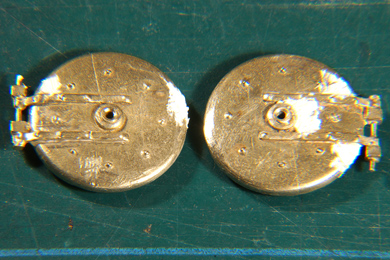
After modelling to shape the smokebox doors are once more sprayed with primer to trace any imperfections. |
The right hand one is still not right at the centre boss. |
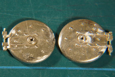
After a second round of smoothing it however is. |
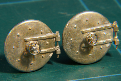 |
The doors were cleaned. Then the handwheels were glued in position, spindle down for the closed position. |
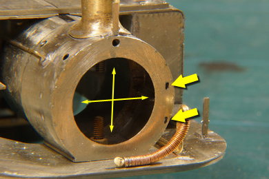 |
At a first attempt to glue the doors, much to my horror I found that the door had a substantial play up and down and left and right in the provided opening. This way the door could not be centred correctly.
I also realised that I left two holes open in which the door hinges would have fit in an earlier version of the kit, before the hinges were cast integrally in the smokebox door. So I will have to do some filling and filing to close the two holes.
|
 |
I measured the opening in the smokebox front (15.0 mm) and the size of the inner ring at back of the casting (13.8 mm). Having 1,2 mm play is simply too much. I cut small shims from 0.5 mm styrene sheet and glued them on the edge of the inner ring. The door would now fit with negligible play. Note: two shims on the left door are at fault, one is completely missing and the other came away. Before fitting the door again I corrected that. |
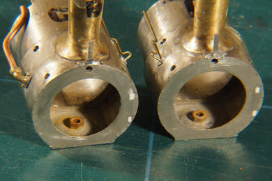 |
The smokebox fronts were soon suitably filled. |
 |
 |
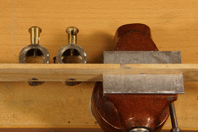
I mounted both smokeboxes on a straight strip of wood. This would make it
To the latter the manual puts rightly so [226] "take a good look to ensure it is correct, or you will always notice it!" |
|
Done! |
|
Cab roof |
|
 |
 |
| As per [174] the roof has a small overhang (left). This is provided to ensure that the roof can be made exactly flush against the cab sheets (right). I should have done this in a much earlier stage but I forgot or postponed it for some reason. Anyway it turned up when checking the manual so I did it now. No harm done that I forgot, it only takes a little more care avoiding the pipes, but it is a delicate and careful job anyhow. It is also a job of inner peace and quiet. Turn on some soft, nice music and go for it. It took me thirty minutes of filing for each side. | |
Spectacle platesAs the manual hardly goes into detail on how to make these spectacle plates I will elaborate on the subject. |
|
 |
|
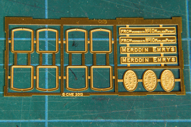
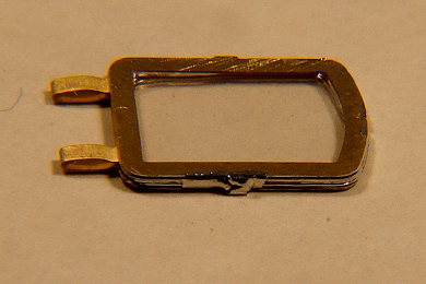
There are two sets of spectacle plates present in the frets: in nickel silver on the standard fret of the superstructure and in brass in the separate fret with the name and works plates. I considered the nickel silver versions superfluous as the final spectacle plate will be from brass. So I used them to make a trial version. Never waste an opportunity to practise before you jump. The manual states that the spectacle plates are designed to take up 10 thou acrylic sheet, 0.25 mm. I had only 20 thou / 0.5 mm but it fit well in the nickel silver version, so I wondered why the manual would state otherwise. I was a bit suspicious about that as the manual is always right (rule #1). I also found the nickel silver result overly thick with 1.1 mm overall thickness. Then it dawned on me that the brass sheet might be thinner. I measured and yes it was! The brass version is only 0.3 mm thickness and allowing for some tolerance it will only take up 10 thou sheet. Better, but I must obtain that first. |
|
|
Nevertheless making the nickel silver version taught me some invaluable lessons.
|
The second attempt already showed a marked improvement, now with 10 thou clear sheet which I was able to obtain at short notice at my local hobby shop, 't Oude Station (the Old Station). Again I learned a valuable lesson. Do not try cut the clear sheet in one big cut despite being only 0.25 thick. It will result in creasing and tearing however slight.
That way you will have absolutely clean edge. A few other tips
|
|
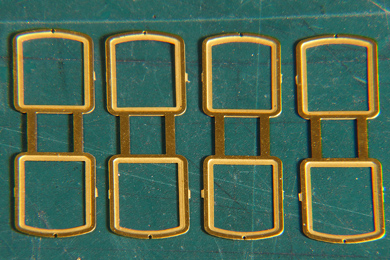 |
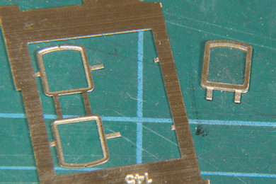
First the etches are cut out of the fret. Be gentle as the material is very thin. Use a sharp blade on a hard underground. Cut as close to the frames as you can. Do not try to remove the etch cusps and the remains of the tabs at this stage. The frames are too vulnerable and you will have to file the frames after soldering anyway. |
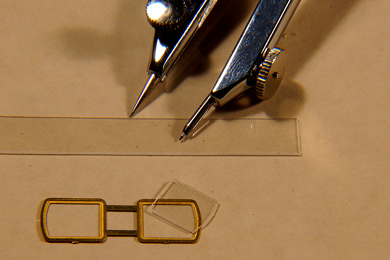 |
Measure the width of the frames on the inside of the recess and cut a strip of sufficient length and of the appropriate width from 10 thou (0.25mm) clear sheet. I did not measure in absolute mm's but used my recently acquired Haff dividers to transfer the measures. Much easier and more accurate. The curve of the upper end of the window has its centre on the bottom of the frame so you can easily use the dividers to draw it on the sheet. Trial fit and work the acrylic until it happily falls into the recess. |
 |
Once the acrylic fits, fold the two halves together so that they sit absolutely flush on top of each other. Carefully align all sides to match each other. Pinch the connecting tabs together but do not completely fold them together for two reasons:
|
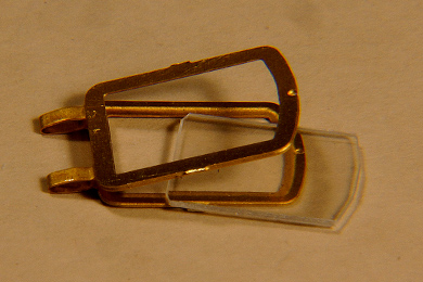 |
Pry open the two halves with a sharp blade and insert the acrylic inset. See to it that it nicely falls into the recess, it should if you have worked carefully, and press the frame halves together. If the they do not come together the acrylic is at fault. Do not force but rework the acrylic until a good fit is achieved. |
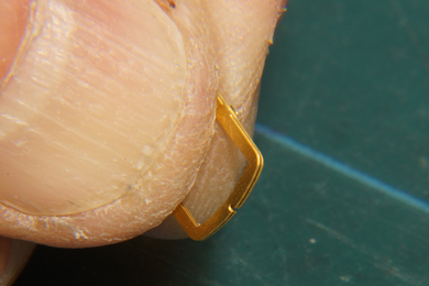 |
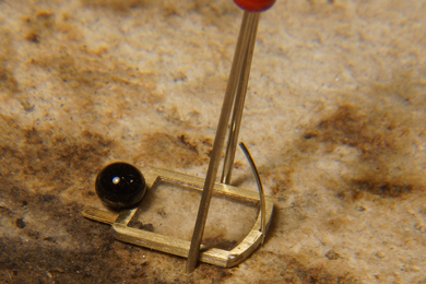
Like so. Now comes the tricky part: soldering brass while having the vulnerable plastic inside! I used 140C solder and set the soldering iron to 220C (a tad higher than with the nickel silver trial as brass needs a bit more punch). With this temperature the acrylic will melt. So how to now that the brass is not getting too hot? Well, hold it between your fingers like on the photo while soldering. As long as you can hold the frame between your fingers, the brass is not too hot! Flux well, use tiny amounts of solder and only short and quick passes of the iron. That will do the trick. |
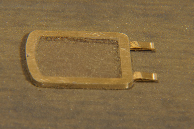
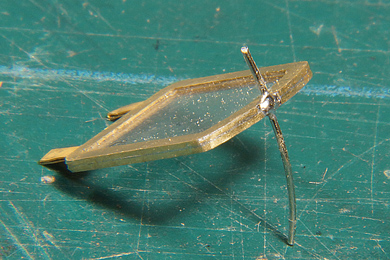
Directly after soldering |
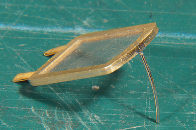
and then after filing and sanding. |
Then file and sand the frame until the brass side shows up again. Remember that you did not remove the cusps and tabs? Well while working on the frame now you can take the cusps and tabs away as well. Now is also the time to pinch the bottom tabs together completely (visible on the next photo) |
|
 |
Sand the front and back on 1200 waterproof emery. Be careful though to press on the frame only and not on the acrylic inset. Also take great care when removing the sanding residue with a soft brush to avoid scratching of the acrylic. Rinsing it with water proved to be a safe method, which also removes flux residues. |
 |
Open up the hole for the curved top latch.
The latches are made by winding a 0.3 mm nickel silver wire around a "rod" of 10 mm diameter (I used a felt pen). The springiness of the nickel silver will make it into a circle of about 17-18mm. Cut a full circle in four quarters.
Nail the spectacle plate down on the soldering pad and insert the latch pushing it partially into the pad. This way you have your hands free for a last quick solder. |
 |
 |
Then cut the part of the latch that stuck into the soldering pad, file and sand smooth. Done! |
|
 |
Final adjustment of the tabs and latches will be done when the spectacle plates are mounted after painting. For now they are carefully stored in a separate box until they are needed during final assembly. |
 |
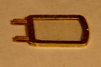
The result will approximately look like this |
|
When writing this paragraph I mused on the photo above and on the still relative thickness of the result. I suddenly realised I could have taken another road.
This way you end up with spectacle plates only half the thickness and you will avoid soldering near the acrylic. You also have four frames a spares. In hindsight I might have chosen this road because the result will be much thinner. But what's done is done. |
|
Lamp irons |
|
Top side ©2011 |
Bottom side ©2011 |
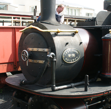
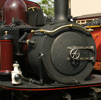
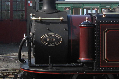
| The lamp irons are not mentioned in the manual but can be found on the frets anyway. Determining the position of the top lamp iron was pretty easy: straight in the middle of the smokebox in front of the stack (duhuh). Determining the location of the lamp irons on the apron proved to be harder then I thought at first sight. Both lamp irons are on the driver's side, so much is clear. To determine the exact position I needed two views. And again my irrepressible urge to make photo's without end paid off. | |
|
|
First I found a broadside view almost straight on the lamp iron. Photo from the manual DVD used with kind permission of Paul Martin ©2013 EDM Models |
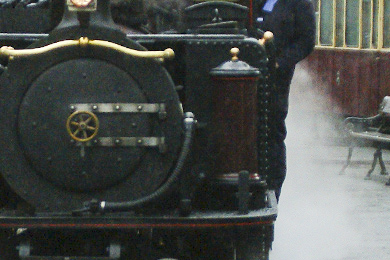
and second I found a head on photo in my own collection which was one of a series of eight or so which I made in 2011 when Merddin Emrys pulled into Tan-y-Blwch in most dreadful weather, hence the poor quality of the detail shot. |
The conclusion from the photos was
That being said, I could complete this chore. |
|
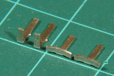
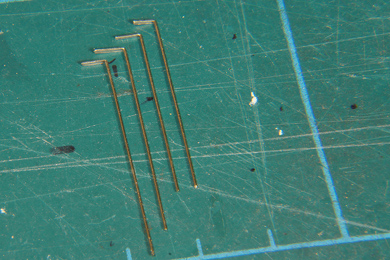
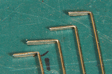
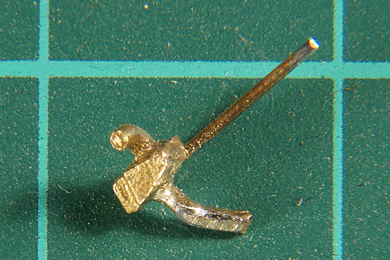
The readied lamp irons. 1x1 cm squares demonstrate their tinyness. |
Soldered in position |
Work is easy and demands no other special comments than that the top lamp iron's base is curved to follow the smokebox shape |
|
Handrails |
|
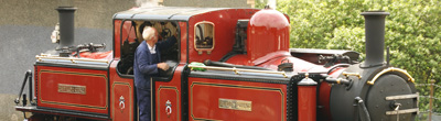
A shot from ME in 2017 |
Next to each cab side sheet there is a blank metal hand rail. On top is a flat piece of sheet metal to keep in place. [180-183] The manual recommends to bend 0.5 mm nickel silver wire and solder it into the provided etches recess in the back of the cab side sheet. This would result in a curves angle and the top metal would not be flat. I tried to mimic the flat top by first flattening the nickel silver wire in a pair of pliers and then bending it over as sharply as possible.
|
 |
The cab sides are put into place with a dot of Blu-tack and the handrails is likewise added. Then the top is soldered. The sides are kept removable to accommodate the painting of the cab interior, so they are stored in a safe place. |
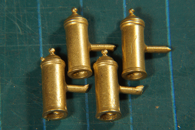
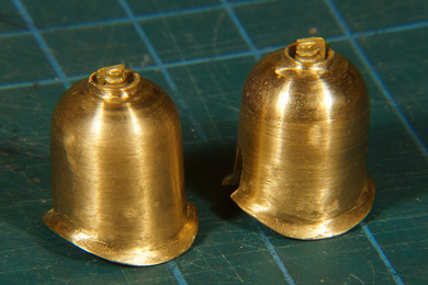
Sandpots |
|
 |
 |
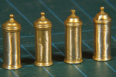 |
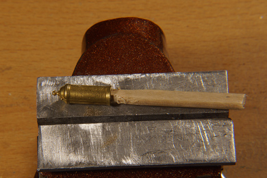
Not much to be said about the sandpots. They need errrm sanding (!), after being filed flush. The only thing of note is that I used a tapered stirring stick on which I pressed the sandpot pretty hard. This way I could on them easily. Again they are not installed, but kept separate until after the painting process as they are very much in the way of the airbrush. |
 |
But what after the locomotive and the sandpots have been painted? Two problems arise.
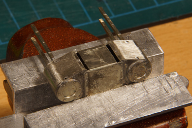
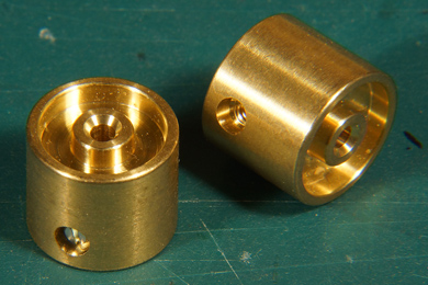
So out came the saw table and I sawed four pieces of brass pipe of just a few tenths of a mm under the width of the inside of the sandpots. |
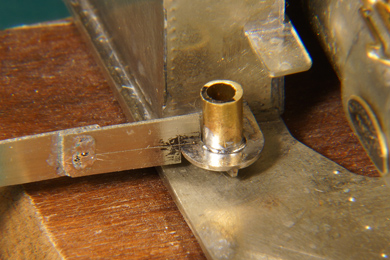 |
I soldered to the placeholders to the pads for the sandpots, using a self made tool to position them exactly. Once in place I kept them there pressing on them with that tool and soldered them. With just enough solder to flow in there is no cleaning to do other then to remove the flux. Do not linger to long with the iron though. The pad is soldered with 188C solder and working to long means it can come away. Touch, flash and go. |
 |
Now the sandpot is always exactly on the predetermined right spot. The placeholder will not be painted so the sandpots will have a firm metal to metal glue bond. Both issues solved! I will put the glue on the inside of the pot so it wil stick to the placeholder and not to the pad so as a bonus I have minimised the risk of glue spillage onto the pad. |
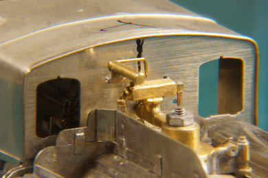
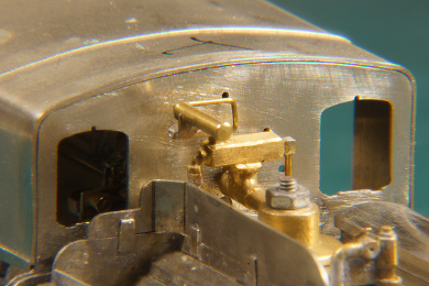
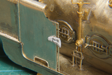
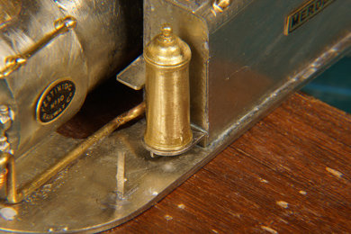
Safety valves |
|
 |
The safety valves are glued with 5 min epoxy as they very difficult to get to with a soldering iron. They are set so the the lever points towards the stack but that does not need to be necessarily so. I have lots of photos where they point in any direction. I just found it neat to arrange them forward.. Like the sandpots the domes are not installed, but kept separate until after the painting process as they are very much in the way of the airbrush. |
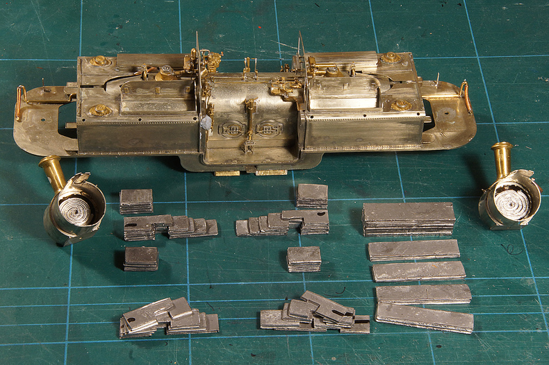
Adding weight |
|
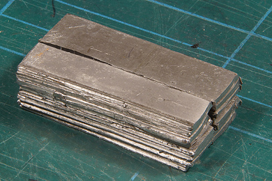
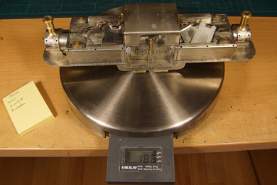
| The superstructure is not very heavy, 186 grams without the bogies, and to make the locomotive a serious puller it will need some weight to be added. I had 1 mm thick lead in store so I loaded the loco where ever I could | |
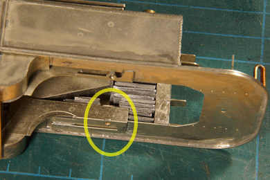 |
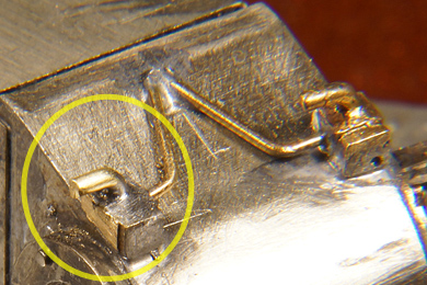
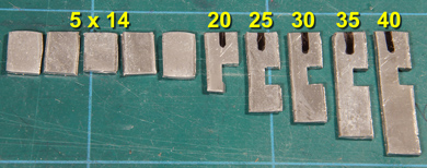
First I added lead on the firemen's side where the coals chute is in the way. I made strips of 40, 35, 30, 25 and 20 mm to fit under the chute once piled. The black mark indicates the top front side of each sheet, to enable easy working. On top of the first five layers I made a pile of five layers of equal size to fit in front of the shut. I took care to provide a gap for the bolt that will secure the bogie to the frame (circle) |
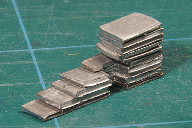
Piled up it looks like this |
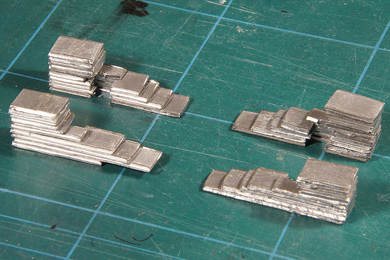
Before long I had four identical sets |
| Resist the temptation to fill the driver's side tanks completely, because the balance of the loco will be disturbed. That is why I made four identical sets. | |
 |
Lead filler for the bottom of the firebox. It is split in two halves so I can feed it through the front and rear openings of the firebox. If I had kept the ash pans removable (as designed) I would not have needed to do so because I could have accessed the firebox from below. Well, that's life.
I also made two coils to fill the smokeboxes. Again do not be tempted to fill the entire boiler front. If you want to fit the motor with a flywheel you will need that space! |
The original loco body weighs 186 gram. |
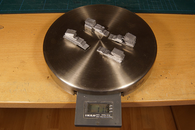
110 gram in the tanks |
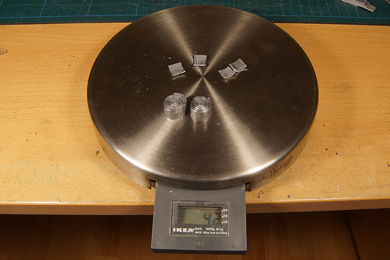
42 grams in the fireboxes |
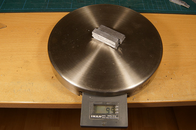
and 95 gram in the firebox |
| which should result in a grand total of 433 grams. | |
The whole lot together. I glued the five lower weights for the driver's side tank together before inserting them in the tank and inserted them in one piece in the tank. I did the same with the five small top pieces. On the firemen's side I inserted the five lower strips one by one because the coal shut. made it impossible to insert more than one at a time. Everything was glued with epoxy. |
|
Total weight 429 grams, so I lost 4 grams on the way because I had to make some alterations to make everything fit. Nevertheless I more than doubled the weight of the loco. |
|
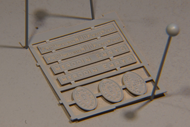
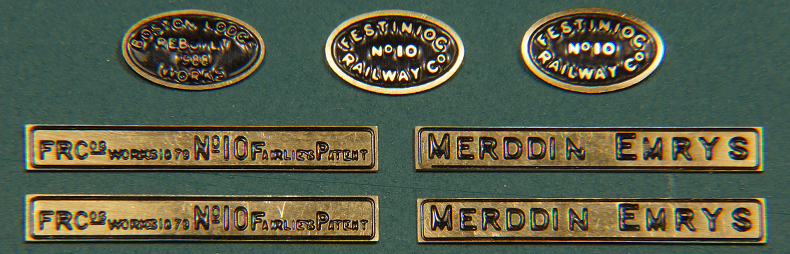
Name and works platesI could postpone the work on the name and works plates until after the painting. But vanity demands that I put name and works plates on the locomotive for the recording of the finished but unpainted locomotive as I always do. On the other hand I can not take the plates out of the fret unpainted because painting them afterwards is difficult. So I will now paint them, attach them temporarily, use them for the photo session of the completed locomotive, remove them and then store them until the painting process has been completed. O vanity of vanities... |
|
 |
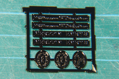 |
To obtain a black lettering the name and works plates were sprayed, first in a base coat and than black. The result was left to set fully for 24 hours. After that the plates are carefully sanded with 400 grit paper until the letters show up correctly and remaining paint is gone. Then the plates are sanded smooth with 800 and 1200 grit paper. |
|
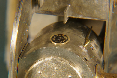 |
The works plate are to be fit on the round smokebox. Although small the plates are big enough to who small gaps on either side.
|
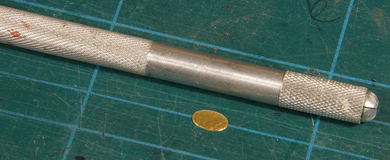 |
Rounding them can be done by rolling a suitable metal bar over them, in this case a knife holder of only 8 mm. The cutting mat is a bit flexible and gives way a little so the brass will be bent if you apply pressure. Roll gently but firmly. The part is small enough to need considerable pressure before bending. Make sure the bar is correctly lined out with the length of the works plate. |
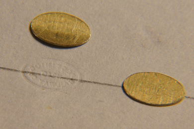 |
I rolled them on a sheet of paper, to protect the painted surface. Under the paper is the cutting mat. As a result the paper was "watermarked". You can clearly see the difference between a rolled and a flat works plate. |
 |
Now the works plate sit absolutely fab on the smokebox. It is those little details that make or break a model. |
Some corrections are needed but the result is satisfying. |
|
Rework cylinder cocks |
|
 |
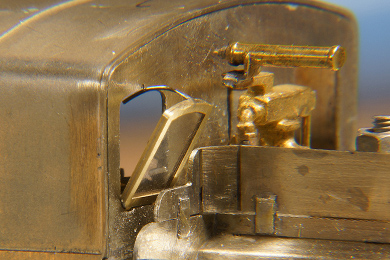
The manual clearly warns to check if the cylinder cocks clear the rail. Instruction [197] says "The steam operated types (for Merddin) need to be fitted carefully to ensure they are not lower than the wheel treads, otherwise they will foul pointwork."
I did not heed that advise and found that out much later. The photo needs no explanation
|
The idea was to file the cocks skew. |
Soon the cylinder blocks were freed of their too low hanging fruit. |
Apart from skewing the spigot also needed filing round. |
Soldered back in place. |
The drain pipes were also bent a little closer to the valve body and now the cocks clear the rail well enough. |
|
 |
When doing the second cylinder set the cylinder cocks's drain pipe broke off. I drilled a 0.7 mm hole and soldered a piece of 0.7 mm brass rod in which I had angled at 90 degrees. |
 |
In the event it proved to be the best depiction of the eight cylinder drain pipes! I had to resist the temptation to break off the other seven as well. |
Motors |
|
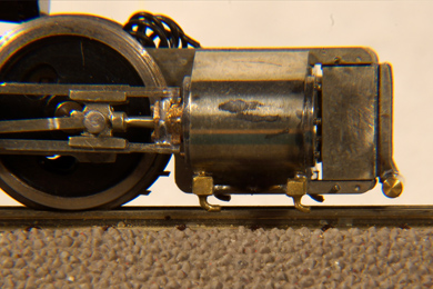
The motors are finally wired up ensuring that each unit runs in the right direction when applying current. Then the units are interconnected which two extra wires that will run through the firebox. For disassembly a pin and plug connection is added. This electrical interconnection of the bogies results in superior behaviour of the loco on less than favourable track. One bogie will feed the other if it looses contact, avoiding any hick-ups, where the loco would have two hick-ups, one time for each bogie, when it passes a currentless spot. |
|
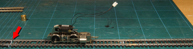
Then follows a test run of the wired bogies |
|
|
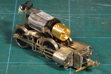 |
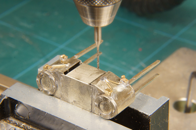
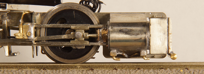
| I bought two flywheels from Markits (MFLYdl12-102DL) and bolted them to the other motor axle. The inside diameter of the boiler is wider but you should also consider the freedeom of movement the bogie needs. Generallt I am not very confident about such small flwheels, weighing about 8 grams each I do not expect them to show much running out. I layed a piece of track, of which I made a part currentless. and drover the unit at maximum speed into that part. | |
|
|
Top without flywheel, a bogie runs just short of 15 cm to come to a stop. But don't forget this only applies when running at full speed. So no, I don't it will make much difference |
|
Done |
|
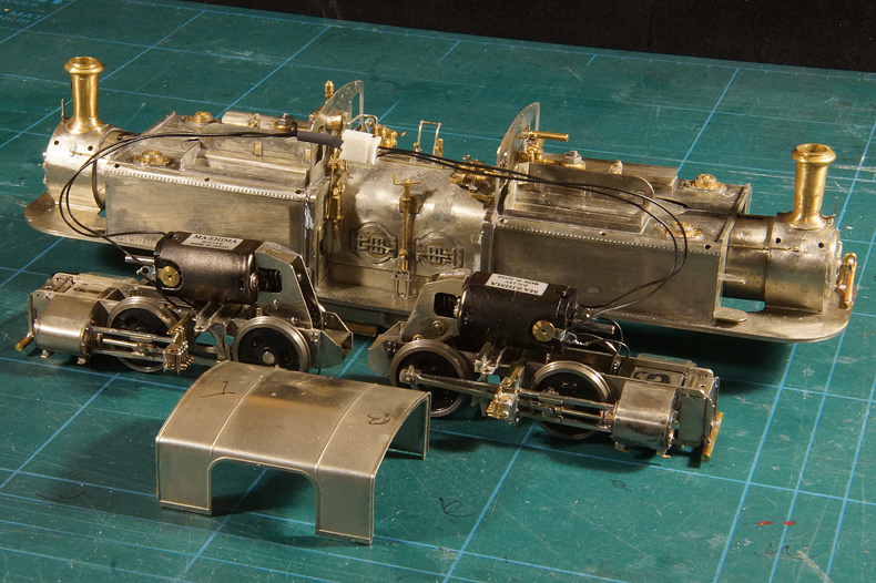
Now the locomotive is down to four major components
and seven sets of small parts, to be added after painting
Assembly is dead easy and completes the build of the wonderful kit. |
|


Sign my
GuestBook