Garrattfan's Modelrailroading Pages
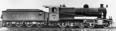
NBDS 118-119
Detailing of the locomotive

| With the locomotive and tender completed in their main structure it is now time to start detailing. | |
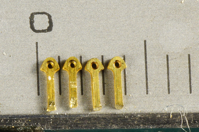 |
The lifting eyes for the cab roof are incredibly tiny |
 |
They were drilled out with a 0.4 mm drill and then threaded on a piece of wire to prevent them from escaping while sanding the etch cusps from the top sides. |
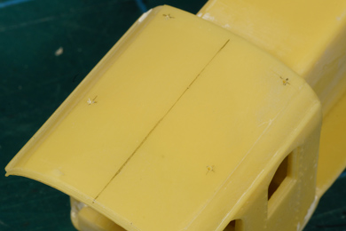 |
Measuring out the desired locations |
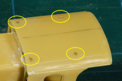 |
And glued into place |
 |
|
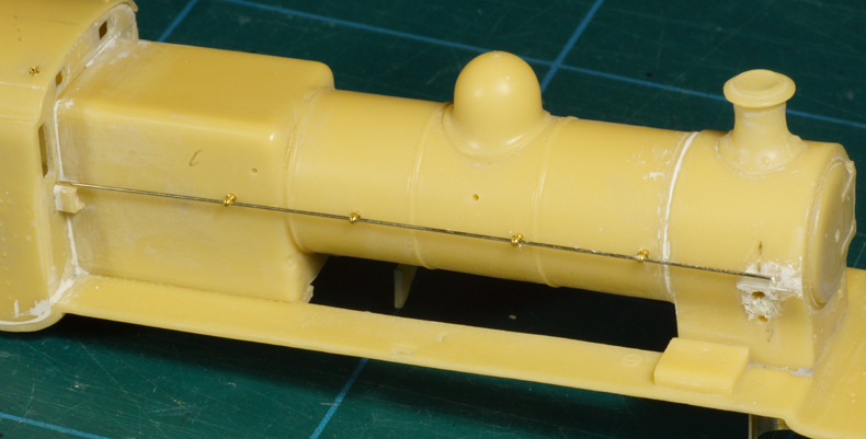
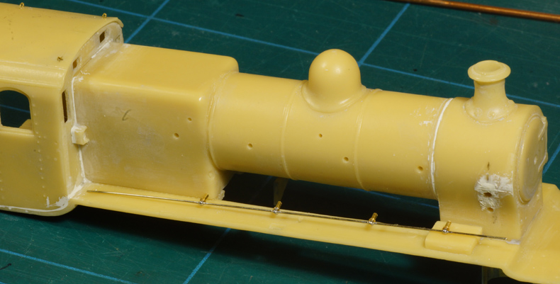
Bending the first handrails. These rails are kept separate until after painting, saving greatly on masking. |
|
 |
 |
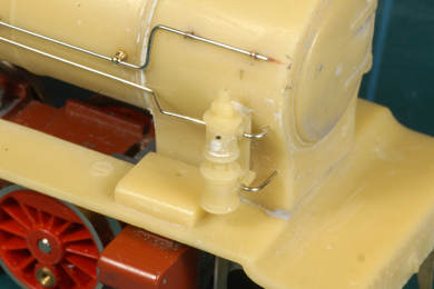
| The airpump and the piping on the right side were made | |
 |
 |
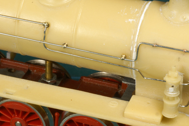
| Left side piping added. The square end piece was not included in the kit so I made it myself. | |
 |
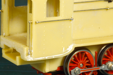 |
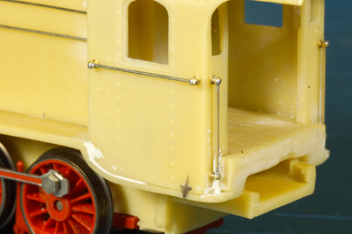
| Handrails of the cab | |
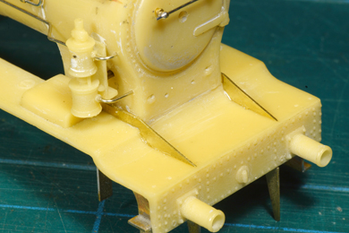 |
Front frames glued in place ... |
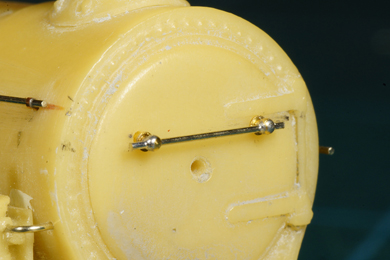 |
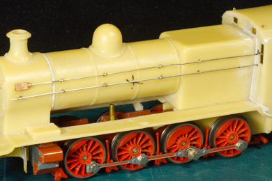
... as well as the smokebox handrail. |
 |
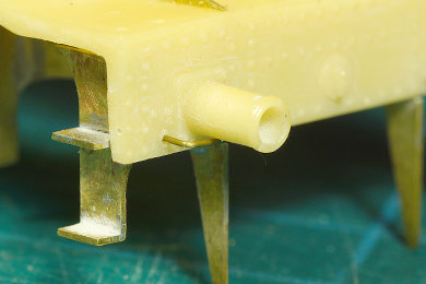
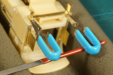
The grip below the buffer was first bent from 0.33 mm brass in a U-shape and glued in place |
 |
 |
| After setting of the epoxy they were bent down in an approximation of a correct angle. | |
 |
 |
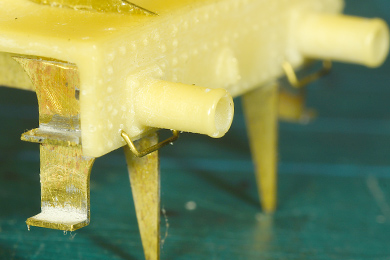
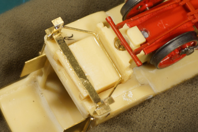
Next the manual tells you to retrieve the plastic lifting arms from the donor BR57 and fit them on the running board. I struggled for some time to comprehend how they were supposed to fit...... until it dawned on me that the manual forgot to mention that the lifting arms were to be reversed. Once that was clear I opened up the tiny slot so the plastic pin of the parts would fit.
|
|
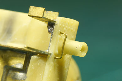
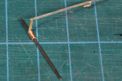
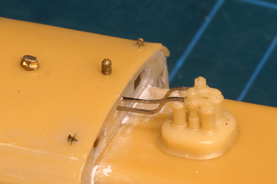
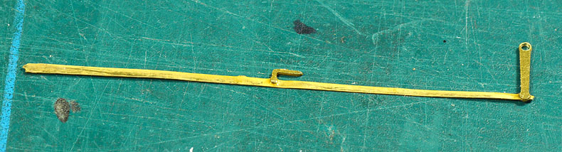
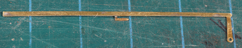
The reach rod is etched down to 0.3 mm. Too thin to be practical. It bends in every direction ... except the one you that want. |
|
So I soldered a slightly tapered strip of 0.3 mm brass on it, and bent it perfectly straight. |
|
 |
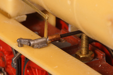 |
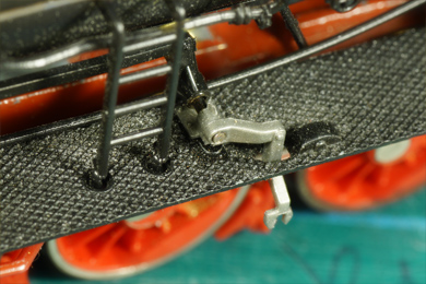
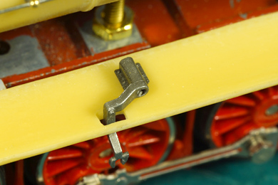
| I soon found that the reverse arm wobbled on the rod to the lifting arm so I added a piece of brass tube to steady it. Once painted it will hardly be visible. | |
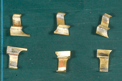 |
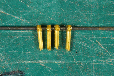
Steps for the locomotive cab (right) and tender front (middle) and tender rear (left). |
 |
 |
 |
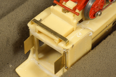
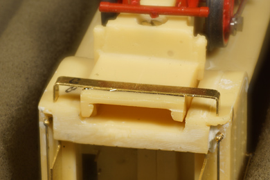
The steps below the cab need to be separable from the cab itself so I bent a strip od 0.5 mm brass to size and glued the steps to the strip. A rod of 0.7 mm served as brace for further strengthening |
 |
 |
 |
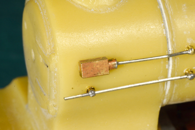
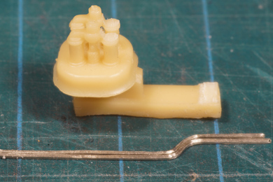
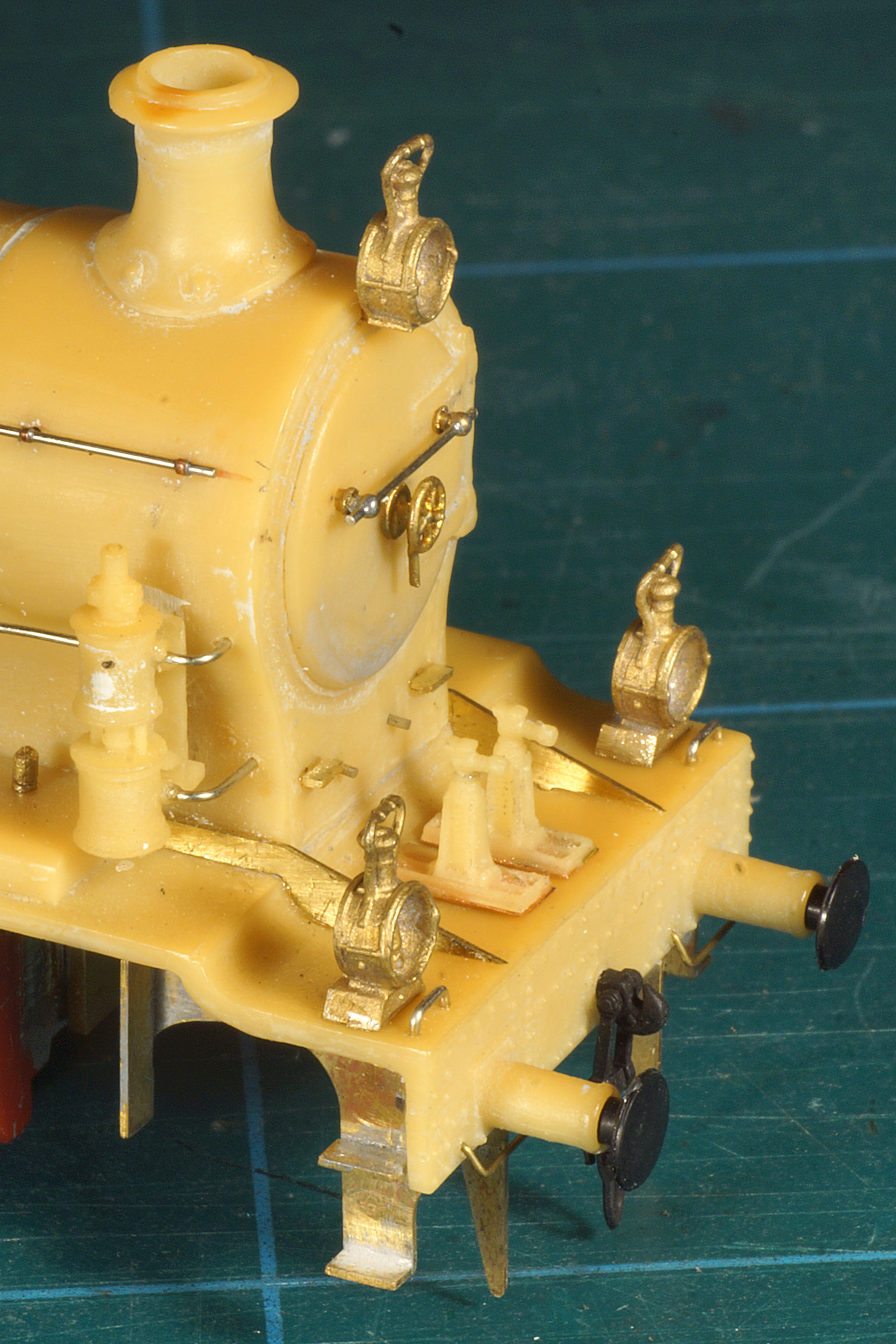
The safety valves where a bit of a problem. The levers to the cab were very thin and likely to break. The manual said to be cautious about it, well one was broken when it came out of the box.
I took a piece of 0.5 mm nickel silver wire and flattened that square with my pliers (at the very bottom of the photo) |
 |
I removed the original levers and bent two from the squared nickel silver. I drilled two holes in the safety valves ... |
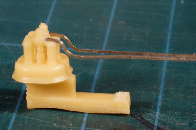 |
... and glued the new levers in place |
 |
Nice job! (If I may say so myself) |
 |
To conclude detailing I installed
|

Sign my
GuestBook